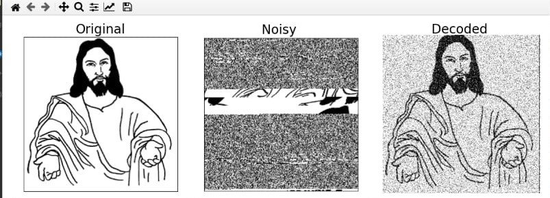
Gallery
Check Out Some of The Photos.


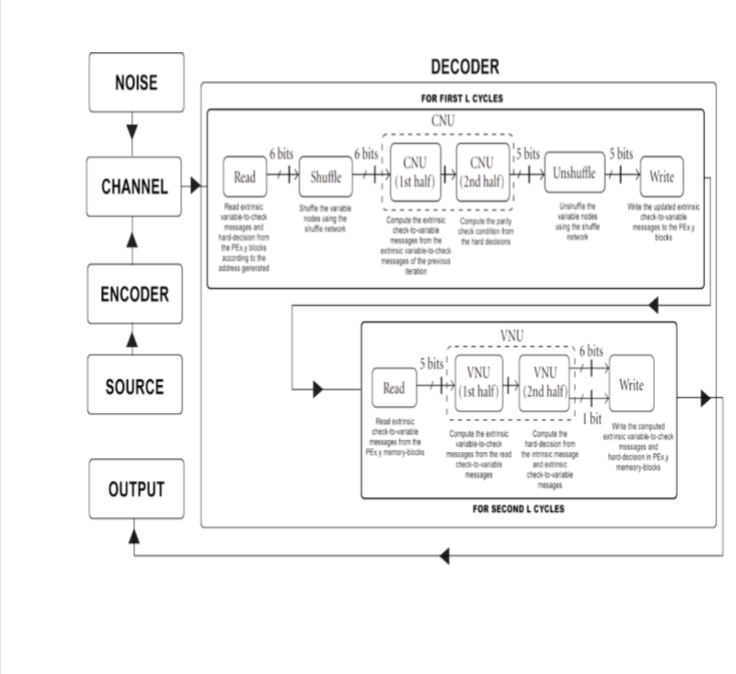
Decoder Implementation
We implemented a (3, 6)-regular LDPC code partly parallel decoder for L = 256 usingXilinx Virtex-E XCV2600E device with the package FG1156. The corresponding LDPCcode length is N = L·k2= 256·62 = 9216 and the corresponding code rate is 1/2.We obtain the constrained random parameter set for implementingπ3and each AG(3)x,yas follows: first generate a large number of parameter sets from which we find few setsleading to relatively high Tanner graph average cycle length, then we select one set leadingto the best performance based on computer simulations.

Architecture
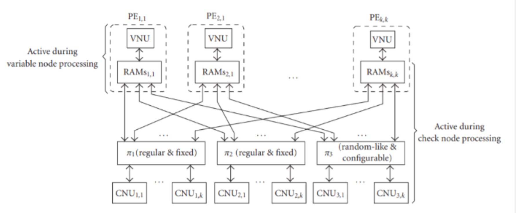
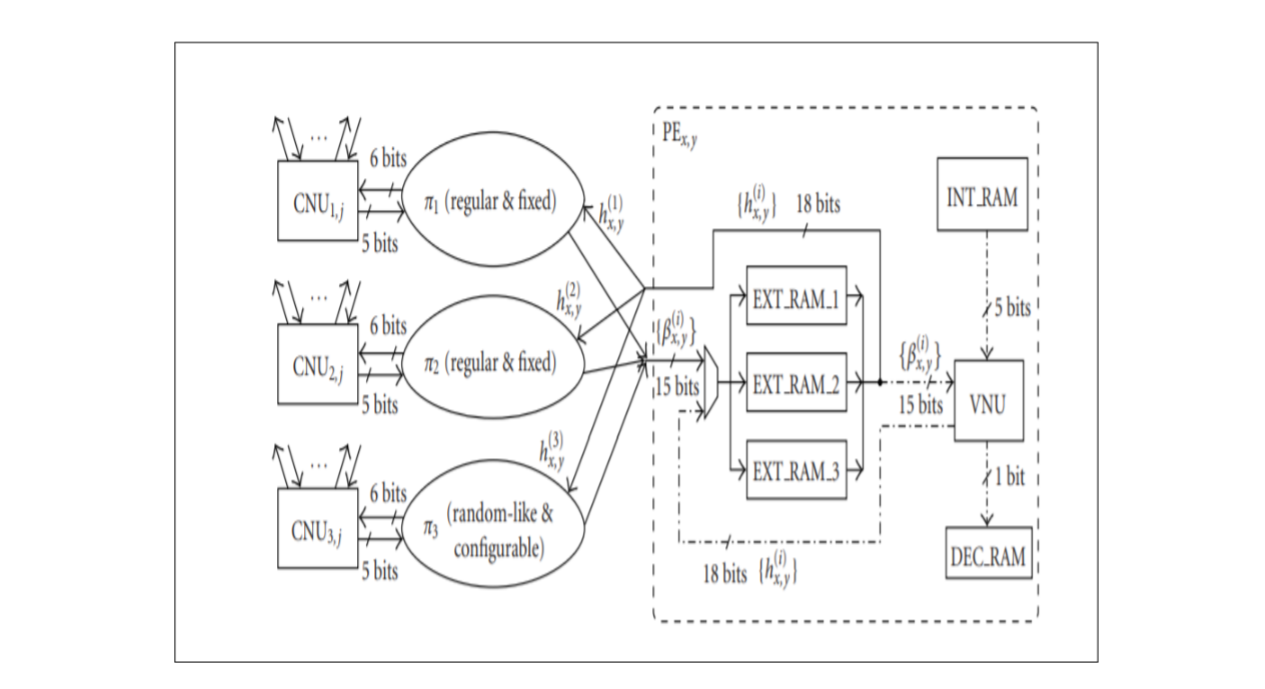
1. Memory Banks: Each PE block PEx,ycontains five RAM blocks:
EXT-RAM-ifori=1, 2, 3, INT-RAM, and DEC-RAM. Each EXT-RAM-ihas
L memory locations and thelocation with the address d-1
(1≥d≥L) contains the extrinsic messages exchangedbetween the
variable node vx,ydin VGx,yand its neighboring check node in
CGi. TheINT-RAM and DEC-RAM store the intrinsic message and
hard decision associated withnode vx,ydat the memory location
with the address d-1 (1≥d≥L).
2. Address Generator: One address generator AG(i)x,yassociates
with one EXT-RAM-iineach PEx,y. In the check node processing,
AG(i)x,ygenerates the address for readinghybrid data and, due
to the five-stage pipelining of datapath loop, the address for
writingback the check-to-variable message is obtained via
delaying the read address by five clockcycles.

Architecture
3. Shuffle Network: A bi-directional shuffle networkπiis
implemented to realize the parity-check matrix H with the
address generators AG(i)x,y.11
4. CNU: Each CNU carries out the operations of one check node,
including the parity checkand computation of check-to-variable
extrinsic messages.
5. VNU: Each VNU generates the hard decision and all the
variable-to-check extrinsic mes-sages associated with one
variable node.
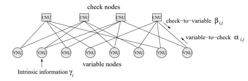
Tanner Graph
Defined as the null space of a very sparse M×N parity-check matrix H, an LDPC code istypically represented by a bipartite graph, usually called Tanner graph, in which one set of Nvariable nodes corresponds to the set of codeword, another set of M check nodes corresponds tothe set of parity-check constraints and each edge corresponds to a nonzero entry in the parity-check matrix H. (A bipartite graph is one in which the nodes can be partitioned into two sets,X and Y, so that the only edges of the graph are between the nodes in X and the nodes in Y.)
